obdexpress
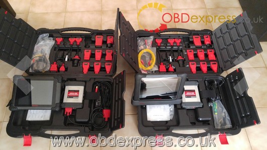
AUTEL MaxiSys Elite feedback: better than many diagnostic & service tools
Le 10/12/2018
Many users feedback they prefer AUTEL MaxiSys Elite to Ford IDS, Snap On’s scanners, verus & MS908P. Here we go to read what they say.
- Being a 30-years Ford Master Technician, I prefer AUTEL MaxiSys Elite to VCM IDS. I never once have I had an issue with the Blue Tooth connection between the scanner and the VCM unlike what we use at Ford. Programs keys perfectly, bi-directional controls work flawless and is very fast processing of live data….WAY faster than Snap On Versus and the software especially for Ford is almost identical to Fords software with the IDS we use at the dealership…I actually prefer my Autel over the IDS now.
Power charge and update: The scanner can be charged with the charge cable or you can plug the charge cable into the stand and then simply set the scanner in and out of the stand as needed and it stays charged when docked between uses. I have it set up on my shops WiFi and it lets me know when there are updates and they update often which I also like.
The same as Snap On’s scanners: The scanner can also be used as a tablet, has great resolution and does everything Snap On’s scanners do for a fraction of the price!
Wide coverage with every adapters: AUTEL MaxiSys Elite is a nice heavy unit, not cheap and doesn’t feel cheap in your hands, comes with about every adapter you could ever need foreign and domestic for PCM hook up and can be easily expanded for oscilloscope and other options.

- AUTEL MaxiSys Elite compares with verus:
I could do everything the verus can do and more since it comes with the passthrough, performs bi directional tests even turn on the wippers or honk the horn. Every test imaginable can be made with the maxisys pro or elite for 1/3 of the price of a new verus. Only real downside is that you have a troubleshooter in the verus scanner and with the autel you have a forum where you post every problem or doubt and other members of the autel comunity will help and give you solutions to your problems. Not a big problem but easily resolved with mitchell or all data.
Ive had a maxisys pro since it can out it has performed flawlessly , perfect. I own a small repair shop ranging from american to import vehicle from gas to diesel (ford powerstroke & dodge cummins) and have never had problems.
- AUTEL MaxiSys Elite compares with MaxiSYS Elite MS908P
In all my 12 years as a tech I’ve used different scan tools and had never seen one as good as the maxisys pro and elite.
I will be posting photos of the differences between the new Elite and the Pro (which I use every day on my shop)
The screen is brighter because is retina display (much like an ipad).
The bootup process is very faster than the pro. The pro aprox 30 secs of boot up and 5-8 secs on the elite.
It has one more usb that is very useful for connecting a mouse or a keyboard.
On the outside you will see is much thinner, lighter and rubber protection (feels more like hard plastic but its rubber) on the sides not on the corners like the pro (which are real rubber).
On the top right corner there is a LED light that indicates the battery life which is great when you have the screen off. On the pro you have to turn the screen on to see battery life.
The elite come with a docking station where you can charge it or leave it out of harms way.


And more and more good feedback.
Hope this post help those who are interested in AUTEL MaxiSys Elite, but have no ideal if it is worth the money.
 Commentaires textes : Écrire
GM MDI serial number: How to get new serial
Le 06/12/2018
RX), pin 2 goes to PC RX (MDI TX). Pin 3 goes to ground. Then when you boot:
(r13006)
RAM Configuration: TRITON 270 II
Bank #0: a0000000 64 MB
Bank #1: a4000000 64 MB
HW Configuration: (0x207) MDI VCI with SMSC9116
Found P30 Flash, unlocking all blocks: 130
Flash: 16 MB
In: serial
Out: serial
Err: serial
Hit any key to stop autoboot: 0
$ help
? – alias for ‘help’
askenv – get environment variables from stdin
autoscr – run script from memory
base – print or set address offset
bdinfo – print Board Info structure
boot – boot default, i.e., run ‘bootcmd’
bootd – boot default, i.e., run ‘bootcmd’
bootm – boot application image from memory
bootp – boot image via network using BootP/TFTP protocol
cmp – memory compare
coninfo – print console devices and information
cp – memory copy
crc32 – checksum calculation
dhcp – invoke DHCP client to obtain IP/boot params
echo – echo args to console
erase – erase FLASH memory
exit – exit script
flinfo – print FLASH memory information
flock – physical lock of Strataflash
funlock – physical unlock of Strataflash
go – start application at address ‘addr’
help – print online help
iminfo – print header information for application image
imls – list all images found in flash
increnv – increment environment variables
itest – return true/false on integer compare
loadb – load binary file over serial line (kermit mode)
loads – load S-Record file over serial line
loop – infinite loop on address range
macaddr – display or store MAC address in Strataflash
mapadd – add a memory map item
mapdel – delete a memory map item
mapinfo – display the memory map information
md – memory display
mm – memory modify (auto-incrementing)
mmcinfo – get info on mmc(sd) card
mtest – simple RAM test
mw – memory write (fill)
nfs – boot image via network using NFS protocol
nm – memory modify (constant address)
ping – send ICMP ECHO_REQUEST to network host
pinit – PCMCIA sub-system
printenv- print environment variables
protect – enable or disable FLASH write protection
rarpboot- boot image via network using RARP/TFTP protocol
reset – Perform RESET of the CPU
run – run commands in an environment variable
saveenv – save environment variables to persistent storage
serialnum – display or store serial number in Strataflash
setenv – set environment variables
sleep – delay execution for some time
test – minimal test like /bin/sh
tftpboot- boot image via network using TFTP protocol
version – print monitor version
The problem is the serial number and MAC flash partitions are misaligned from
the flash erase block boundaries, which forces them to mount read only. Because
of this the update commands don’t work

$ serialnum

Serial number: 1220-22129579

$ serialnum 1220-12345678

Error: start address not on sector boundary

Failed to read same serial number back from Strataflash
I think that if we mapped a memory partition at 0x00FE0000 with size 0x00020000
then we would be able to erase that partition and load a new one via ethernet /
tftp. This 128k block would cover both the serial and mac paritions. Both these
partitions have checksums which would need to be figured out and calculated.
serial and mac are changed in flash then a re-flash of the device should put
the new numbers in the registry and they should persist over device firmware
updates. I expect duplicate mac addresses are as relevant as the serial number
duplicates on your lan.
Name Location Size Type Source Guard
—- ——– —- —- —— —–
boot 0x00000000 0x00040000 Flash bootargs Off
bootvars 0x00040000 0x00020000 Flash bootargs Off
linux1 0x00060000 0x00180000 Flash bootargs Off
initrd1 0x001e0000 0x00600000 Flash bootargs Off
linux2 0x007e0000 0x00180000 Flash bootargs Off
initrd2 0x00960000 0x00600000 Flash bootargs Off
linuxvars1 0x00f60000 0x00020000 Flash bootargs Off
linuxvars2 0x00f80000 0x00020000 Flash bootargs Off
serialnum 0x00ff0000 0x00008000 Flash bootargs Off
macaddress 0x00ff8000 0x00008000 Flash bootargs Off
zImage 0xa0008000 0x00200000 DRAM Initial Off
scratch 0xa2000000 0x00a00000 DRAM Initial Off
script 0xa2a00000 0x00100000 DRAM Initial Off
Stack 0xa3e9ff80 0x00020000 DRAM System On
GD 0xa3ebff80 0x00000080 DRAM System On
Heap 0xa3ec0000 0x00040000 DRAM System On
Text 0xa3f00000 0x000218f0 DRAM System On
BSS 0xa3f218f0 0x00005c34 DRAM System On
The sdcard is just the /usr/local/ portion of the firmware. The rest is in the
16mb flash.
Mount the sdcard parition 1 under linux, and rename telnetd.sh-disabled to
telnet.sh in /bin. While there I also edited the init script and added this
near the start to make the prompt nicer:
Access u-boot (38400 baud, see previous post), and at the prompt type:
addprimary;setenv bootargs ${bootargs}
mtdparts=flash0:256k(boot),128k(bootvars),1536k(linux1),6144k(initrd1),1536k(linux2),6144k(initrd2),128k(linuxvars1),128k(linuxvars2),32k@16320k(serialnum),32k(macaddress),128k@16256k(id);
The MDI will boot and start a telnet server on its IP and have a new flash
partition configured as /dev/mtd10 called ‘id’. This will align with the erase
block so can be updated. Check in /var/log/messages for the presence of ‘id’
without it being forced readonly.
have setup on your lan.
[root@mdi tmp]# dd if=/dev/mtd10 of=mtd10.img
256+0 records in
256+0 records out
[root@mdi tmp]# ls -l mtd10.img
-rw-r–r– 1 root root 131072 Jan 1 00:07 mtd10.img
[root@mdi tmp]# ftpput -u <user> -p <pass>
<ip> mtd10.img mtd10.img
Now load up mtd10.img on your pc in HxD or Hexworkshop. The serial is at
0x10000 with a crc32 checksum of 0x10000->0x17FFB at 17FFC (LSB).
checksum feature of the hexeditor to calculate crc32 the sums of of the ranges
and save the new sums in the bin (remember to enter them in LSB format).
[root@mdi tmp]# ftpget -u <user> -p <pass>
<ip> mtd10-new.img mtd10-new.img
[root@mdi tmp]# cd /usr/local/mtd/
[root@mdi mtd]# ./flash_unlock /dev/mtd10
[root@mdi mtd]# ./flash_erase /dev/mtd10
Erase Total 1 Units
Performing Flash Erase of length 131072 at offset 0x0 done
[root@mdi mtd]# ./flashcp /tmp/mtd10-new.img /dev/mtd10
[root@mdi mtd]# dd if=/dev/mtd10
of=/tmp/mtd10-readback.img
256+0 records in
256+0 records out
[root@mdi mtd]# md5sum /tmp/mtd10-new.img
/tmp/mtd10-readback.img
1a1f4fb7db878218c558b45c0db50c9f /tmp/mtd10-new.img
1a1f4fb7db878218c558b45c0db50c9f /tmp/mtd10-readback.img
Now reboot the MDI,
and hold down the power button so it goes in to recovery mode. Use MDI manager
to recover the device. Once completed it’ll have the new serial and mac.
the same serial anymore. But if you already have one then you can do this
yourself, so long as your careful and make sure everything is going to plan and
makes sense to you as you go.
https://mhhauto.com/Thread-GM-MDI-serial-number?)
RX), pin 2 goes to PC RX (MDI TX). Pin 3 goes to ground. Then when you boot:
(r13006)
RAM Configuration: TRITON 270 II
Bank #0: a0000000 64 MB
Bank #1: a4000000 64 MB
HW Configuration: (0x207) MDI VCI with SMSC9116
Found P30 Flash, unlocking all blocks: 130
Flash: 16 MB
In: serial
Out: serial
Err: serial
Hit any key to stop autoboot: 0
$ help
? – alias for ‘help’
askenv – get environment variables from stdin
autoscr – run script from memory
base – print or set address offset
bdinfo – print Board Info structure
boot – boot default, i.e., run ‘bootcmd’
bootd – boot default, i.e., run ‘bootcmd’
bootm – boot application image from memory
bootp – boot image via network using BootP/TFTP protocol
cmp – memory compare
coninfo – print console devices and information
cp – memory copy
crc32 – checksum calculation
dhcp – invoke DHCP client to obtain IP/boot params
echo – echo args to console
erase – erase FLASH memory
exit – exit script
flinfo – print FLASH memory information
flock – physical lock of Strataflash
funlock – physical unlock of Strataflash
go – start application at address ‘addr’
help – print online help
iminfo – print header information for application image
imls – list all images found in flash
increnv – increment environment variables
itest – return true/false on integer compare
loadb – load binary file over serial line (kermit mode)
loads – load S-Record file over serial line
loop – infinite loop on address range
macaddr – display or store MAC address in Strataflash
mapadd – add a memory map item
mapdel – delete a memory map item
mapinfo – display the memory map information
md – memory display
mm – memory modify (auto-incrementing)
mmcinfo – get info on mmc(sd) card
mtest – simple RAM test
mw – memory write (fill)
nfs – boot image via network using NFS protocol
nm – memory modify (constant address)
ping – send ICMP ECHO_REQUEST to network host
pinit – PCMCIA sub-system
printenv- print environment variables
protect – enable or disable FLASH write protection
rarpboot- boot image via network using RARP/TFTP protocol
reset – Perform RESET of the CPU
run – run commands in an environment variable
saveenv – save environment variables to persistent storage
serialnum – display or store serial number in Strataflash
setenv – set environment variables
sleep – delay execution for some time
test – minimal test like /bin/sh
tftpboot- boot image via network using TFTP protocol
version – print monitor version
The problem is the serial number and MAC flash partitions are misaligned from
the flash erase block boundaries, which forces them to mount read only. Because
of this the update commands don’t work
$ serialnum

Serial number: 1220-22129579

$ serialnum 1220-12345678

Error: start address not on sector boundary

Failed to read same serial number back from Strataflash
I think that if we mapped a memory partition at 0x00FE0000 with size 0x00020000
then we would be able to erase that partition and load a new one via ethernet /
tftp. This 128k block would cover both the serial and mac paritions. Both these
partitions have checksums which would need to be figured out and calculated.
serial and mac are changed in flash then a re-flash of the device should put
the new numbers in the registry and they should persist over device firmware
updates. I expect duplicate mac addresses are as relevant as the serial number
duplicates on your lan.
Name Location Size Type Source Guard
—- ——– —- —- —— —–
boot 0x00000000 0x00040000 Flash bootargs Off
bootvars 0x00040000 0x00020000 Flash bootargs Off
linux1 0x00060000 0x00180000 Flash bootargs Off
initrd1 0x001e0000 0x00600000 Flash bootargs Off
linux2 0x007e0000 0x00180000 Flash bootargs Off
initrd2 0x00960000 0x00600000 Flash bootargs Off
linuxvars1 0x00f60000 0x00020000 Flash bootargs Off
linuxvars2 0x00f80000 0x00020000 Flash bootargs Off
serialnum 0x00ff0000 0x00008000 Flash bootargs Off
macaddress 0x00ff8000 0x00008000 Flash bootargs Off
zImage 0xa0008000 0x00200000 DRAM Initial Off
scratch 0xa2000000 0x00a00000 DRAM Initial Off
script 0xa2a00000 0x00100000 DRAM Initial Off
Stack 0xa3e9ff80 0x00020000 DRAM System On
GD 0xa3ebff80 0x00000080 DRAM System On
Heap 0xa3ec0000 0x00040000 DRAM System On
Text 0xa3f00000 0x000218f0 DRAM System On
BSS 0xa3f218f0 0x00005c34 DRAM System On
The sdcard is just the /usr/local/ portion of the firmware. The rest is in the
16mb flash.
Mount the sdcard parition 1 under linux, and rename telnetd.sh-disabled to
telnet.sh in /bin. While there I also edited the init script and added this
near the start to make the prompt nicer:
Access u-boot (38400 baud, see previous post), and at the prompt type:
addprimary;setenv bootargs ${bootargs}
mtdparts=flash0:256k(boot),128k(bootvars),1536k(linux1),6144k(initrd1),1536k(linux2),6144k(initrd2),128k(linuxvars1),128k(linuxvars2),32k@16320k(serialnum),32k(macaddress),128k@16256k(id);
The MDI will boot and start a telnet server on its IP and have a new flash
partition configured as /dev/mtd10 called ‘id’. This will align with the erase
block so can be updated. Check in /var/log/messages for the presence of ‘id’
without it being forced readonly.
have setup on your lan.
[root@mdi tmp]# dd if=/dev/mtd10 of=mtd10.img
256+0 records in
256+0 records out
[root@mdi tmp]# ls -l mtd10.img
-rw-r–r– 1 root root 131072 Jan 1 00:07 mtd10.img
[root@mdi tmp]# ftpput -u <user> -p <pass>
<ip> mtd10.img mtd10.img
Now load up mtd10.img on your pc in HxD or Hexworkshop. The serial is at
0x10000 with a crc32 checksum of 0x10000->0x17FFB at 17FFC (LSB).
checksum feature of the hexeditor to calculate crc32 the sums of of the ranges
and save the new sums in the bin (remember to enter them in LSB format).
[root@mdi tmp]# ftpget -u <user> -p <pass>
<ip> mtd10-new.img mtd10-new.img
[root@mdi tmp]# cd /usr/local/mtd/
[root@mdi mtd]# ./flash_unlock /dev/mtd10
[root@mdi mtd]# ./flash_erase /dev/mtd10
Erase Total 1 Units
Performing Flash Erase of length 131072 at offset 0x0 done
[root@mdi mtd]# ./flashcp /tmp/mtd10-new.img /dev/mtd10
[root@mdi mtd]# dd if=/dev/mtd10
of=/tmp/mtd10-readback.img
256+0 records in
256+0 records out
[root@mdi mtd]# md5sum /tmp/mtd10-new.img
/tmp/mtd10-readback.img
1a1f4fb7db878218c558b45c0db50c9f /tmp/mtd10-new.img
1a1f4fb7db878218c558b45c0db50c9f /tmp/mtd10-readback.img
Now reboot the MDI,
and hold down the power button so it goes in to recovery mode. Use MDI manager
to recover the device. Once completed it’ll have the new serial and mac.
the same serial anymore. But if you already have one then you can do this
yourself, so long as your careful and make sure everything is going to plan and
makes sense to you as you go.
https://mhhauto.com/Thread-GM-MDI-serial-number?)
- Commentaires textes : Écrire
BMW ISTA+ Diagnosis PAD Mode: How to Activate
Le 05/12/2018
BMW ISTA+ Diagnosis PAD Mode all detailed can be found here:
What is the PAD mode on ISTA?
PAD is the short form of Testing analysis diagnosis.
The PAD mode is the vehicle condition between “Residing” and “Driving”.The PAD mode corresponds to the physical “terminal 15 on”.
In the PAD mode, all the control units as well as all physical terminals are on.
Why do you need the PAD mode?
A new terminal control concept was introduced to the new G12 7 series vehicle
In order to switch the vehicle into diagnosis mode (Terminal 15 in the past), either for diagnosis with ISTA or programming or coding with ISTA/P, the Start/Stop button needs to be pressed 3 times in succession within .8 seconds. The vehicle will then switch over to diagnosis mode (PAD) Testing Analysis Diagnosis. In order to switch the vehicle into diagnostic mode for the State Inspection Maintenance Program, the Start/Stop button must also be pressed 3 times in succession within .8 seconds. Additionally if a diagnosis session is started with ISTA and the vehicle is in “Residing” mode, ISTA automatically switches the vehicle to diagnosis mode (PAD).
How to activate PAD mode:
The PAD mode is activated as follows:
– Press the START-STOP button three times within 0.8 seconds.
– Via a diagnosis order.
If you put in PAD mode before starting diagnosis, it should come up as PAD. ISTA shows PAD after doing this.
Note: During vehicle diagnosis, a vehicle with Parking-Residing-Driving is automatically placed in the pad mode.This is also displayed in ISTA in the top right.This ensures that a diagnosis can be performed with all control units.
How to diagnose a BMW is ISTA PAD mode:
During vehicle diagnosis, a vehicle with Parking-Residing-Driving is automatically placed in the pad mode.This is also displayed in ISTA in the top right.This ensures that a diagnosis can be performed with all control units.

How to use the selective partial network in PAD mode:
In vehicles today, there are up to 70 control units which are networked with each other.Depending on the current vehicle condition or the user’s wishes, not all of the comfort systems and assistance systems are always required. By specifically switching off and activating the control units that aren’t required, so-called selective partial network operation, energy can be saved, the battery relieved and due to this its life increased. For vehicles with a combustion engine, the electrical energy consumption is indirectly coupled to the fuel consumption through the alternator. Here, the selective switching off of control units that are not required can contribute to the reduction of the fuel consumption and therefore the CO2 emissions.
The master for the selective partial network operation is the Body Domain Controller (BDC).The control units which are not required are switched off via a corresponding bus signal.
In order to realise partial network operation for control units, other transmit/receive systems are used.The transmit/receive systems are able to evaluate and interpret messages.As long there is bus communication and no valid wake-up signal for the corresponding control unit, this control unit remains switched off.If a valid wake-up signal for the corresponding control unit is sent on the bus, the transmit/receive system can activate the voltage regulator of the microcontroller and the control unit starts.The control unit is switched off by the deactivation of the voltage regulator.
Note: The individual partial networks can be activated and deactivated via diagnosis orders. All partial networks are active in PAD mode.
Is there problems if using ENET cable instead of ICOM in this mode?
Yes, only get pad resident etc, with icom a2, not with enet or usb to obd2
- Commentaires textes : Écrire
Diagbox 7.83 changes a language, How to?
Le 04/12/2018
Lexia-3 Lexia3 V48 PP2000 V25 with Diagbox V7.83 supports multi-Language: English, German, French, Japanese, Russian, Spanish, Portuguese, Swedish, Turkish, Dutch, Polish, Italian, Hungary, Greek, Czech ,
Here, Notice of how to change a language for lexia-3 Diagbox 7.83
Having installed your language and keyboard in Windows and set the non-Unicode programs to revert to the preferred language in System Locale, you can change the language in DiagBox releases up to v7.72 through the menu and manually for later releases.
However, I think the point missed in your case is setting the language for “non-Unicode” programs, shown in the first snapshot. You probably need to be connected to the internet for some updates. You can revert back to English US later and still work with your language.
Notice that it works on all Windows (XP, 7, 8 and 10) as well as all DiagBox versions (7.57 and 7.72 are shown in the attached snapshots).


Who Like This Article Also Viewed:
- How to change language in Lexia3 PP2000 DiagBox v7.76 v7.77 (3)
- How to use Lexia-3 PP2000 XS Evolution to Program New Keys for Peugeot (2)
- Lite Version Lexia-3 V48 Diagnostic with Diagbox V7.76 Software (2)
- How to install Lexia 3 lexia-3 DiagBox V7.76 software (2)
- GM MDI clone works with Ford IDS: Confirmed! (2)
- Commentaires textes : Écrire
Ford VCM2 IDS Windows 10 Migration Tips & Guides
Le 30/11/2018
Here you will get to know how to migrate an Ford IDS System to Windows 10.
Part 1: Reason why you should do the migration
Part 2: Preparation before Windows 10 Migration
Part 3: Windows 10 Migration
Part 1: The reason why you should do the migration
Windows 10 migration on a PC that has IDS installed requires preliminary steps to ensure successful operation. Migrating to Windows 10 without following the procedure below may result in connection concerns with your VCM or VCM II to IDS, IDS license concerns, or an inability to properly install/uninstall IDS on your PC.
You may want to consider remaining on your current Operating System or having an IT professional perform the Windows 10 update.
Part 2: Preparation before Windows 10 Migration
- Begin by uninstalling IDS. Click on the Windows Icon > Ford Motor Company > IDS > Uninstall IDS, as

Next, select the “Remove” option on the screen

- When prompted, select “Return License”

- Next, uninstall the Bosch Software. Click on the Windows Icon > Control Panel > Programs and

- Select the Bosch VCI Software, and then click on “Uninstall”

- Once the Bosch VCI Software has been successfully uninstalled, reboot your
Part 3: Windows 10 migration
After you have completed the above steps, your system is ready to migrate to Windows 10. Go to the following URL for Microsoft’s Windows 10 update instructions:
Technical support from http://www.obdexpress.co.uk
- Commentaires textes : Écrire